SBRdac | Performance Test of the Squeezebox Receiver™
Block Diagram
Below is a simple block diagram that shows audio signal and clock paths of the system.
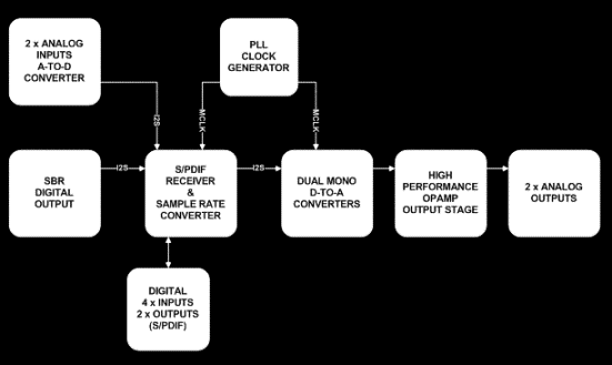
Audio signal comes from the internal I2S output of SBR and goes to the sample rate converter.
This is also the S/PDIF receiver and is also connected to the analog input.
The sample rate converter changes the samples rate (selectable - up to 192kHz) and syncronizes to a master clock.
This master clock comes from a high quality PLL device and is also used for the DACs.
The DACs are a mono setup with one DAC per channel.
The analog stage consists of opamps.
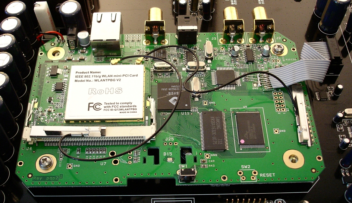
SBR Signal
The audio signal is connected by a flatcable to the resistors on the SBR DAC I2S inputs.
This taps out the same signal stream as the SBR onboard wolfson DAC.
The SBR has its own three stage 9V supply
Analog-to-Digital Converter
The board has 2 analog and 4 digital inputs - and 2 digital outputs.
The analog input is made with a PCM4202 ADC from Texas Instruments (TI).
This is an high performance 24bit analog to digital converter, one of the best available.
It has pre-stages of TI OPA1632 fully differential in/output opamps.
Output sample rate is selectable, from 44.1kHz to 192kHz.
The ADC has local 5V and 3.3V power supplies.
The analog stage has 2 inputs: unbalanced (RCA/phono) and balanced (XLR) - selectable by high grade audio relay.
Sample Rate Converter, Master Clock and Digital in/outputs
The sample rate converter is also one of the best in the business, the SRC4392 from TI.
The RCA receives the I2S signal from the SBR or ADC and up-samples it (if seleceted) and syncronizes it with a master clock. It can up-sample to 192kHz.
This devices has also digital audio inputs and outputs besides being SRC. There are 4 inputs and 2 outputs.
Inputs: RCA/coax standard, RCA/coax professionel, Optical/toslink and AES/EBU (XLR).
Outputs: RCA/coax standard and AES/EBU (XLR).
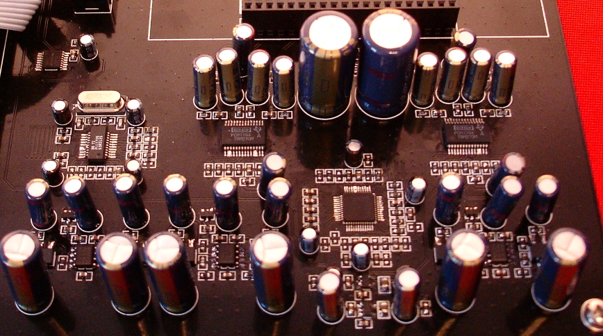
Digital-to-Analog Converters
Digital to analog conversion is made with two high performance stereo DACs, set in mono configuration, so one DAC per channel.
The DACs used is the PCM1794 (hardware controlled version of PCM1792).
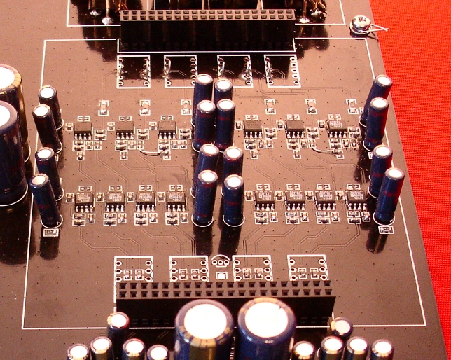
Analog Opamp Output Stage
The analog output stage consist of opamp circuits both for I/V conversion and output buffer.
Relays (not shown on picture) on in and outputs make it possible to "disconnect" the circuits and use another circuit on a daugtherboard.
The daugther board fits the two connector headers.
Power Supply
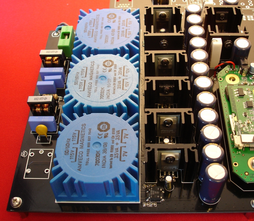
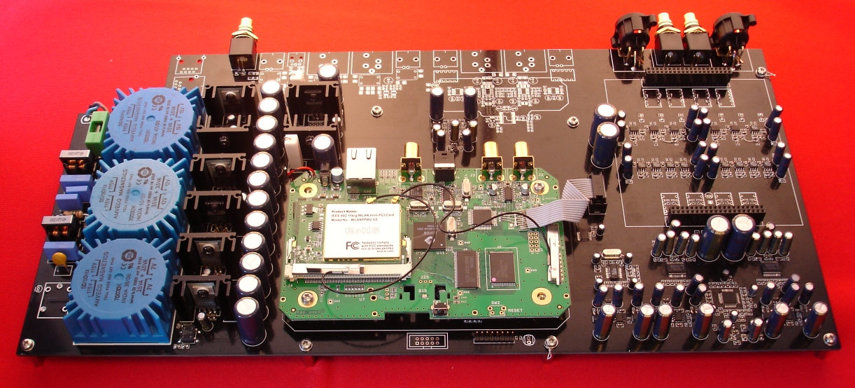
The power supply has a two stage mains filter and uses three separate toroid PCB transformers.
There are eight regulators to makes the needed voltages.